This is an article realized for StarWind blog and focused on the design and implementation of a ROBO infrastructure. See also the original post.
Introduction
The fabric of SAN (means Storage Area Network) with Fibre Channel solutions have always been a dedicated network, with dedicated components (like FC switches).
But, starting with iSCSI and FCoE protocols, the storage fabric could now be shared with the traditional network infrastructure, because at least level 1 and 2 have a common Ethernet layer (for iSCSI also layer 3 and 4 are the same of TCP/IP networks).
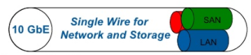
Hosts (the initiators) in a converged network use typically Converged Network Adapters (CNAs) that provide both Ethernet and storage functions (usually FCoE and iSCSI). The results are that LAN and SAN are shared on the same physical network:

Also if it is possible to have a shared network infrastructure both for the storage and the networking, it does not mean that it’s always recommended: a dedicated storage network simplifies the troubleshooting and can minimize throughput bottlenecks.
But with the introduction of 10Gb Ethernet, the bandwidth has become enough to make convergence possible. Anyway, you have to plan that kind of solutions very carefully and work with new standards specific for those kinds of converged networks.
Note that “converged networks” it’s also referred to another type of network protocol sharing: like using VoIP to share the LAN with the phone network.
FC over Ethernet (FCoE)
FCoE is an encapsulation protocol that enables the transport of FC storage traffic over Ethernet frames.
FCoE frames use an EtherType of 0x8906 and FCoE Initialization Protocol (FIP) uses an Ethertype of 0x8914. FIP enables FCoE SAN traffic and legacy LAN Ethernet traffic to be carried on the same link.
FC frames are encapsulated in an Ethernet frame and sent from one FCoE-aware device across an Ethernet network to a second FCoE-aware device.
The FCoE-aware devices may be FCoE end nodes (E-nodes) such as servers, storage arrays, or tape drives on one end and FCoE Forwarders on the other end. FCoE Forwarders are switches that provide SAN fabric services and may also provide FCoE-to-FC bridging.
CNA
Converged network adapter (CNA), also called a converged network interface controller (C-NIC), is a network card that combines the functionalities of a traditional Network Interface Controller (NIC) with other storage-specific functions, like FCoE or iSCSI Host Bus Adapter (HBA).
In other words, it “converges” access to, respectively, a storage area network and a general-purpose computer network.
Early products were marketed around 2005 with the term C-NIC which combined iSCSI storage functionality with Gigabit Ethernet. But it’s only with the 10 Gbps NICs that CNA has become popular.
Initially for FCoE:

By Abisys – Own work, CC BY 3.0, https://commons.wikimedia.org/w/index.php?curid=6733983
Why to converge?
Convergence takes the best of both and allows for lossless Ethernet traffic to allow block-based transmission and allows applications that lend themselves to block-based I/O – for example, larger structured databases, which will be ideal candidates for this new converged Network. Convergence simplifies the infrastructure, which facilitates the deployment of high availability solutions and provides the underlying foundation for service-oriented, utility-based computing.
Sometimes is just a need: if you have only two 10 Gbps (or higher) NICs and you cannot (or want) add new cards on your server, the converged solutions maximize your investments, simplify cabling, provide good flexibility.
Also, traditional and legacy architectures limit the growth of data centers in applications, servers, storage, and network traffic. Converged networks can provide customers with a long-term, future-proof strategy to develop a single, converged data center fabric with the flexibility and performance that scales.
Why not?
Dedicated storage networks remain simples to operate just because you have two different silo’es and if you already have separate teams for storage, network and virtualization remain the simplest options.
Converged networks could be a mess when you still have separated teams or if you don’t have specific converged skills. Network skills are not enough and you have to learn more on new protocols and the possible issues that you can have in converged networks.
Converged networks present some challenges and the key aspects that you must address properly are:
- More software depending, mean that you need to check your compatibility properly
- Share at physical level, isolate at logical level
- Define the right QoS and enforce it otherwise, you blend your different traffics
- Use proper switches, full rate is not enough for converged networks
Without those guidelines, converged network can just work, but not properly or with the right service.
Drivers are the key
CNA cards are mostly driven by software elements, including the drivers (one for the network part, and one for each storage functions).
To verify the right match between the firmware (on the card) and the drivers’ version is crucial, to avoid unexpected behavior and issues.

Ethernet is not storage-friendly
The biggest issues for Ethernet storage traffic are the collisions at layer 2 (you can avoid them by using dedicated full rate switches), IP fragmentation (you can avoid it by using the right MTU on the entire communication chain) and the TCP retransmissions.
This implies several risks in using traditional network concepts and configuration in converged solutions.
Network and data center administrators must not simply provide connectivity and bandwidth. They must ensure that each system, function, and application on the network has the amount of bandwidth and network quality of service it needs while attaining interoperability and avoiding bottlenecks.
New protocols are needed to provide a right configuration of your network fabric and more from a traditional Ethernet to a “lossless” Ethernet.
Data Center Bridging (DCB)
DCB is an enhanced Ethernet version that enables the convergence of various applications in data centers (LAN, SAN) into a single interconnected network.
For converged networks, DCB is a must to provide the right quality of service (QoS) for your storage traffic. For dedicated storage networks, you can still have some benefit by using DBC, for example in the iSCSI protocol to avoid TCP retransmissions.
DCB provides network resource sharing mechanisms including bandwidth allocation and lossless traffic. This allows converged network implementations to carry multiple traffic types on the same network infrastructure with fair resource sharing.
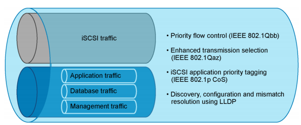
DCB is a set of standards and enhancements to the Ethernet protocols in order to implement a “lossless Ethernet” suitable for storage traffic. There are a lot of concepts, but the most important are:
- VLAN tagging within an iSCSI SAN where DCB configuration values are embedded within the Ethernet header (IEEE 802.1Q).
- Data Center Bridging Capability Exchange (DCBx) is an extension of the IEEE standard 802.1AB for Link Layer Discovery Protocol (LLDP) and provides capabilities, functions and identities advertise using existing LLDP protocol.
- Priority-based Flow control (PFC) is an evolution of Flow Control function, originally implemented in the MAC Pause feature of Ethernet (IEEE 802.3x). The new standard (IEEE 802.1Qbb) manage traffic priority pausing and enablement of lossless packet buffers/queueing for storage traffic.
- Enhanced Transmission Selection (ETS): (IEEE 802.1Qaz) is used to guarantee a percentage of bandwidth or provide minimum, guaranteed bandwidth allocation per traffic class/priority group during congestion and permits additional bandwidth allocation during non-congestion.
- Application priority: support for the storage protocol in the application priority DCBX Type Length Value (TLV). For example, in iSCSI it advertises the priority value (IEEE 802.1p CoS, PCP field in VLAN tag) for iSCSI protocol. End devices identify and tag Ethernet frames containing iSCSI data with this priority value.
With PFC the MAC Pause feature is a simplistic control of traffic made by requesting that the sender stop transmitting for a specific period of time. With no granularity applied to this request, all Ethernet frames are stopped. PFC also asks the sender to stop transmitting, but it, in addition, leverages classes of traffic to apply granularity to the process. In a DCB environment, all traffic is tagged with a Class of Service (CoS) using the VLAN Qtag. PFC can then request that a specific CoS be paused for a time, while other classes can continue unhindered as shown in Figure 2. In a storage environment, this may mean that other TCP/IP traffic is paused, while storage traffic tagged with a higher priority can be managed using PFC.

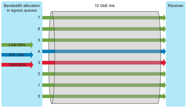
With ETS you can guaranteeing a percentage of bandwidth to a traffic class (TC). A traffic class contains one or more Classes of Service from the VLAN Q-tag. Each traffic class is then assigned a percentage of bandwidth with a granularity of 1%. All traffic class bandwidths must add up to 100%; oversubscription is not allowed. The bandwidth percentage defined is a minimum guaranteed bandwidth for that traffic class. If a traffic class is not using its entire minimum amount, it can be utilized by other traffic classes that may need it. However, as soon as the original traffic class requires its bandwidth again, the other traffic flow must be throttled to allow the bandwidth to be recovered. This is accomplished through the use of PFC discussed earlier. PFC will issue a pause for the overreaching traffic classes in a manner to allow the bandwidth to be regained with a minimum number of dropped frames for the throttled traffic class.
Note: An important note to consider when deciding on bandwidth percentages for each traffic class is that the required accuracy of the ETS algorithm is only plus or minus 10%.
Application priority is a DCB configuration construct which defines the mapping of an application or protocol to a priority (PCP) value. All frames belonging to a particular application or protocol are tagged with a priority value (0 to 7) which in turn gets mapped to a traffic class or priority group (PG). This mapping provides dedicated bandwidth for a protocol and also facilitates PFC with lossless behavior for a protocol across the network. The application or protocol is identified by TCP/UDP port numbers or by an Ethertype number. For example, the iSCSI protocol is identified by TCP port 3260 and FCoE protocol is identified by Ethertype 0x8906. 9 Dell PS Series DCB Configuration Best Practices | BP1058 Protocols identified by this method can be mapped to a priority value using the application priority feature. For example, iSCSI identified by TCP port number 3260 can be mapped to priority 4. An end device which is the source of a frame carrying iSCSI payload marks the frame with priority 4 in the VLAN tag. All devices in the network forward the frame with this priority value and process it with the same configured PFC lossless behavior and PG/TC bandwidth settings for this priority. The default priority value is 0 and any network traffic not assigned a priority value using the application priority feature will have priority 0 marked in the frame.
With DCBx, LLDP relies on the use of Type-Length-Values (TLV) to advertise the device capabilities for a multitude of Ethernet functions, as well as its identity. Currently, both FCoE and iSCSI have Application TLVs. DCBX allows mismatch detection and remote configuration of DCB parameters. Each peer port on a link initially advertises its locally configured DCB parameters. It then verifies the advertised configuration parameters from the remote peer and detects mismatches. DCBX also allows remote configuration of a peer port with the willing mode feature (“auto-discovery”).
The DCBX willing mode feature on end devices enables automatic configuration of end devices and minimizes mismatches on DCB parameters. In this model of configuration, network switches are configured with the required DCB parameters and they advertise the configuration through DCBX to attached end devices. The end devices operating in willing mode learn the DCB configuration information from DCBX and operate with those parameters. The TLV fields within the LLDP protocol are used by DCBX for communicating the DCB parameters. The DCBX TLV exchange between peer ports is illustrated in Figure 5, Figure 6, and Figure 7 below. It is a simple example showing only one port per device to illustrate the DCBX exchange. The server CNA and storage ports are in willing mode (willing = 1) to accept DCB parameters from the switch port. The switch ports are configured with DCB parameters as per deployment requirements and operate with the willing mode off (willing = 0) as shown in Figure 5. In the figures, DCBX TLVs include PFC TLV, PG/ETS TLV, and application priority TLV.

This is quite useful, to manage all DCB configuration at switch level (for example in the core switches), but could be very risky if your CNA (and other switches) are not properly configured.
Actually, also if VMware ESXi has a specific service (DCBD) for DCB protocols (same for Windows Server 2012 and later, with the DCB feature), usually to manage converged network properly you use specific network cards (CNA NICs) and off-load the FCoE or iSCSI traffic on them, providing also DCB support. For most CAN cards, this could be achieved by “partition” the card in multiple virtual functions (using NPAR) and configuring some those functions to support storage protocols. Most storage vendor provides already reference architecture and configuration guide for their storage and verified CNA cards.
Frame size
FCoE also has its own EtherType (0x8906) to distinguish FCoE frames from other Ethernet traffic and ensure the in-order frame handling that FC requires. FCoE frames include:
- 2112 bytes FC payload
- 24 bytes FC header
- 14 bytes standard Ethernet header
- 14 bytes FCoE header
- 8 bytes cyclic redundancy check (CRC) plus EOF
- 4 bytes VLAN header
- 4 bytes frame check sequence (FCS)
The payload, headers, and checks add up to 2180 bytes. Therefore, interfaces that carry FCoE traffic should have a configured maximum transmission unit (MTU) of 2180 or larger. An MTU size of 2180 bytes is the minimum size; some network administrators prefer an MTU of 2240 or 2500 bytes.
For iSCSI usually, jumbo frames are used (MTU 9000) to improve performance, but check the real improvement, because it could be only around 10%.
And if you don’t configure properly the new MTU on the entire network, end-to-end, you will have IP fragmentation (only for iSCSI, because FCoE does not have the IP level at all) with the worst performance.
Multi-paths
For redundancy, you need more devices that imply multiple path networks. Data networks traditionally use the Spanning Tree protocol to connect switches, but Spanning Tree opens up too many connections in a converged network – it broadcasts from one switch to the next to create a congestion point. Also, does not provide active-active paths and could be really limiting in this kind of networks.
TRILL (Transparent Interconnection of Lots of Links) is a new standard and the recommended method of managing multiple links, so switches in the converged network that support TRILL will make your journey much smoother.
But not the only, because you can use switch stacking or virtual chassis or VLT, to have single logical switches span over more physical switches. Or also SDN at underline level with solutions like Cumulus, BigSwitch, Pluribus.